


Resistance value for the standard product at 20°C. Adjustable depending on applied voltage,
duty factor, required torque, etc.
InductanceValue at the rotation angle ϕ = 0°.
Coil saturation temperature rise ΔθsCoil saturation temperature rise during continuous energization in W (Watts).
Coil saturation temperature rise Δθs can be calculated from the following formula.
Proportionality constant K(℃/W) x Continuous energization in W(watt) x Energization ratio(1/f)
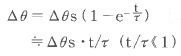
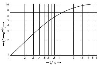
Time constantWhen power is applied to the coil, the current does not instantly flow but increases gradually.
This increase is expressed in factor which is called time constant.
When length of energization becomes equivalent to time constant, the current reaches 63% of
its saturation value. The saturation temperature value Δθs at the time of ![]() can be calculated
can be calculated
by the following formula.
e:base of natural logarithm
Heat-resistant classHeat-resistant temperature of the solenoid depends on the allowable temperature of each insulation
classification of the wire used for the coil.
Standard model of Takano solenoid is class E(120℃). Class H(180℃) custom model is also available.
| Heat-resistant class | Allowable temperature(℃) |
A | 105 |
E | 120 |
B | 130 |
F | 155 |
H | 180 |
Moment of inertia
Moment of inertia of the rotor.
ResponsivityResponsivity is the duration between the starting point of energization and the completion of
rotating motion for specified angle(°). In general, this duration tR for moving the traveling
angle 2φ0 can be calculated by the following formula. Moment of inertia of the load is JR ,
the torque applied to rotate the load is T(φ).
The standard models use ball bearings. Models using oil-less bearings are also available.
(See the model identification table.) Select by duty or other requirements of your application.
Lead wiresLead wires used for our products are UL-certified. Customization such as changing wire length,
attach connectors and other terminal treatment are available.
ShaftThe standard is D-cut. Customization such as keying, tapping or changing size are available.
Coil saturation temperature rise Δθs can be calculated from the following formula.
Proportionality constant K(℃/W) x Continuous energization in W(watt) x Energization ratio(1/f)
In the specification chart of each product, you can find the proportionality constant K(℃/W)
(per electrical power consumption rate) of temperature rise rate.
Below is an example of the calculation.
(Ex.) When RSR20/20 which proportionality constant is K≒7(℃/W), is continuously powered
at 10 W, the coil saturation temperature rise will be:
Δθs≒7(℃/W)×10(W)=70(℃)
The duty factor for 10 ms ON/OFF operation at 10 W will be:
1/f = ON time/(ON time + OFF time) = 10/(10 + 10) = 1/2
Accordingly, the coil saturation temperature rise for these intermittent energization will be:
Δθs≒7(℃/W)×10(W)×1/2=35(℃)
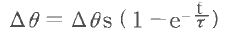
Temperature change in short period of timeThe temperature rise ∆θ at time t after the energization is expressed as formula(1)
 ・・・・・・・(1)
e: base of natural logarithm
When the temperature rise becomes Δθ and then de-energized, the temperature θ’ which is the temperature after time t from the de-energization point can be expressed as formula(2)
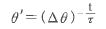 ・・・・・・・・・・(2)
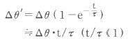
Therefore, when the temperature drop during this duration is Δθ’, this temperature drop rate can be obtained as follows. It is almost the same with formula (1).
The solid line shows the torque generated when rotating from (−ϕ) to (+ϕ) direction while voltage is applied.
When the energizing direction is reversed, it rotates from (+ϕ) to (−ϕ) direction and shows the torque curve as in the dotted line. These solid and dotted curves are symmetrical with the line passing through the position of the rotation angle ϕ = 0°.
The 0-V curve shows the holding force of the permanent magnet during the de-energized state.
The rotational angle ϕ = 0° is normally the center point of symmetrical rotation. In the product drawing, it is shown as where the flat face (D-cut) of the center shaft is oriented.
On each product page, you can find the response speed for each travel angle when there is no load attached (tR ) in the Response Characteristics chart. Moment of inertia of the rotor (Jo) is shown in the Specifications list..
Approximate response speed (t’R) when the load with moment of inertia (JR) is attached to the rotation shaft can be calculated by the following formula.
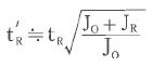
The reason it is said "approximately" is because frictional moment will be added to the moment of inertia in the actual situation. Therefore, it should be tested and measured with the actual application and conditions.