Latching solenoids
Product introduction
Takano Latching Solenoids are self-holding linear latching solenoids which maintain its position only with magnetic force and performs linear axial movement by electrical pulse. It's energy efficient with low heat generation.
There are either bi-stable type or mono-stable type based on the type of circuit.
-
DC-powered to pull in
Pulls in as the coil is energized. Stays in position using the magnetic force of the permanent magnet even after the coil is de-energized.
-
Stays in position using the holding force of the permanent magnets
Stays in the current position even during a power outage.
No locking mechanism required. Moreover, free from problems such as coil temperature rise or heat generation because no holding current is required.
-
Cost efficient
Series List
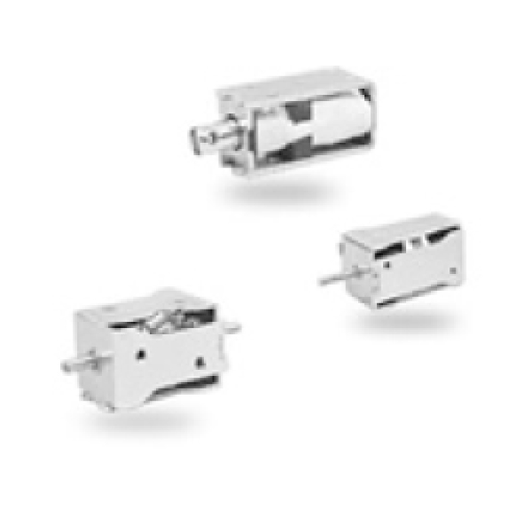
Bi-Stable Latching SolenoidsTSB Series
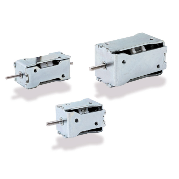
- Requires only energization for reciprocation and stays in position only by the holding force of the permanent magnets on both sides.
- Ideal for use as a drive or multi-contact switch for the flappers in banking terminals or for shutters for optical systems, in particular when high holding force is required.
Applications
- Flapper drive unit for financial instruments, shutter drive unit for optical, medical, and analytical instruments.
- Electric lock opening and closing driver (locker lids, automatic dyeing device lids, sterilizer lids, stationary ashtray lids).
- Tube clamp for medical equipment.
| Model | Dimension(㎜) | DC resistance | Holding force (de-energized) |
Attractive force | Stroke | Documents/Drawings |
|---|---|---|---|---|---|---|
| TSB-0705 | 16×16×35.7 | 10Ω | 3N or more | 3N | 5mm | |
| TSB-0805 | 20×20×30 | 7.5Ω | 5N or more | 5N | 5mm | |
| TSB-1005 | 25×25×45 | 20Ω | 15N or more | 7N | 5mm | |
| TSB-1010 | 25×25×45 | 20Ω | 10N or more | 5N | 10mm | |
| TSB-LS | 25×25×45 | 5Ω | 2N or more | 15N | 5mm |
Structure and Operating PrinciplesTSB Series
Structure
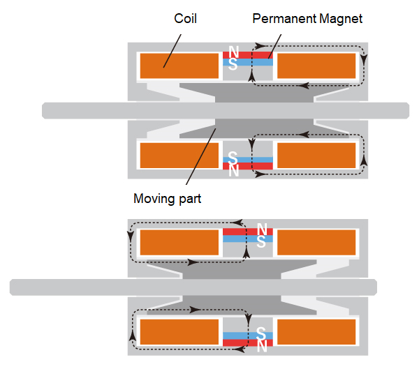
- It is composed of two coils with a permanent magnet located between them. When not energized, the magnetic field of the permanent magnet is generated in the direction of the dotted line shown in the left figure, which enables the position to be held on both sides.
- Stays in the set position even during a power outage. No locking mechanism required. Moreover, free from problems such as coil temperature rise or heat generation because no holding current is required.
Operating Principles
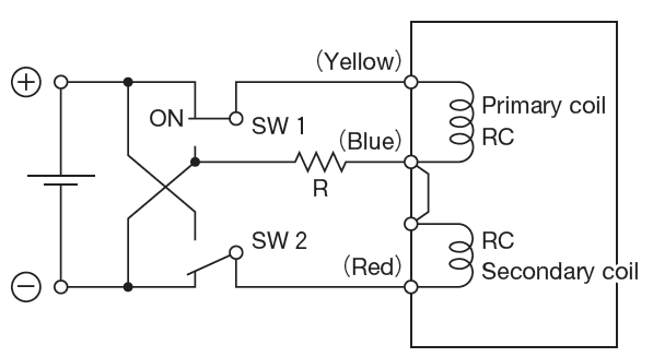
When switch SW1 is turned on
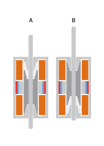
When switch SW1 is turned on(with SW2 off), the shaft is pulled from A to B. Even if switch SW1 is reset the shaft stays in position.
When switch SW2 is turned on
When switch SW2 is turned on(with SW1 off), the switch is pulled from B to A.
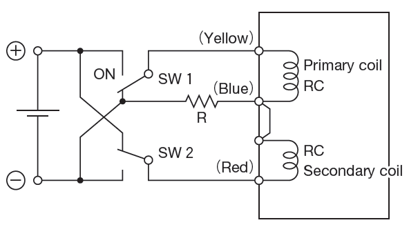
In either case, in order to cancel out the holding power of the permanent magnet on both coils (not just on the holding side), it is necessary to insert an external resistor ( R ) for degaussing. Thus, the unit operates on a two-loop structure.
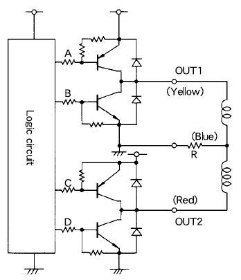
Circuit example
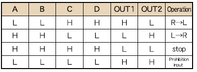
Circuit example for TSB series (referential)
Various circuits for driving latching solenoids have been devised by their users. Following is an example for your reference.
Operational mode