| Rated Voltage | DC 12-24V |
|---|---|
| Operating voltage range | Rated voltage ±5% |
| Applicable product | Proportional solenoid valve |
| Standby power | Less than 1W |
| Interface | Analog (0-5V) Digital (RS485) - Termination Resistance: 120Ω |
| Control Signal Input | Input impedance: Approx. 44kΩ (0-5V) |
| Sensor Input | Input Impedance: Approx. 1kΩ (0-5V) |
| Control signal for the valve | PWM (8kHz) |
| The range of PWM output | 0 to approx. 95% (When a valve resistance of approx. 152Ω is connected to DC +24V, 0 to approximately 150mA output with 0 to 5V signal) |
| Operating Temperature | 5-50°C |
| Ambient humidity for use | 45-85% RH (No condensation) |

| Interface |
A : Analog Specification D : Digital Specification |
|---|---|
| Presence or absence of a case |
Blank: Without case (PCB shape) C: With case |
| Examples |
1)PBCS000-A → Analog specification (without case) 2)PBCS000-D → Digital specification (without case) 3)PBCS000-AC → Analog specification (with case) 4)PBCS000-DC → Digital specification (with case) |
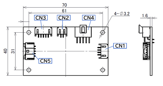
| Identification number | Terminal Description |
|---|---|
| 1 | Proportional Valve Connection (No Polarity) |
| 2 | Proportional Valve Connection (No Polarity) |
| Identification number | Terminal Description |
|---|---|
| 1 | Power |
| 2 | Power Ground (Note 1) |
| 3 | RS-485 Inverted Receiver Input B/Driver Output B (Note 2) |
| 4 | Signal Ground (Note 1) |
| 5 | RS-485 Non-Inverted Receiver Input A/Driver Output A (Note 2) |
| 6 | Not Used |
| 7 | Not Used |
| 8 | Control Signal Input (0-5V) (Note 3) |
| 9 | Not Used |
| 10 | Not Used |
| Identification number | Terminal Description |
|---|---|
| 1 | Sensor Power Supply Output (Note 4) |
| 2 | Not Used |
| 3 | Not Used |
| 4 | Sensor Input (0-5V) |
| 5 | Signal Ground (Note 1) |
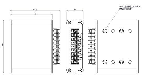
| Identification number | Terminal Description |
|---|---|
| ① | Power |
| ② | Power Ground (Note 2) |
| ③ | RS-485 Inverted Receiver Input B/Driver Output B or Control Signal Input (0-5V) |
| ④ | RS-485 Non-Inverted Receiver Input A/Driver Output A or Signal Ground |
| ⑤ | Sensor Input (0-5V) (Note 3) |
| ⑥ | Proportional Valve Connection (Non-Polarized) |
| ⑦ | Proportional Valve Connection (Non-Polarized) |