A bi-stable rotary solenoid refers to a rotary solenoid with a bi-stable mechanism. Bi-stable means "having two stable states," and our solenoid is characterized by having two stable positions at specific angles.
Bi-stable Rotary Solenoid’s features include high-speed operation and low energy consumption.
-They can be used in the open/close mechanisms of optical instruments and shutters.
-Switching, sorting, and selecting mechanisms of automatic machines.
-And in control of valve opening and closing.
Latching solenoid is a solenoid that has a linear movement. It can maintain its position even when no power is supplied after activation. It switches positions by applying current and returns to its original position with a reverse pulse current, characterized by its excellent energy efficiency.
-Lock Mechanism (Doors, Cabinets, Safety Locks)
Once locked, the mechanism can maintain the lock without power supply, thereby reducing power consumption.
-Switching Mechanism for Automatic Assembly Lines
Can be used for the fixing and releasing of tools and switching the conveyance routes for parts.
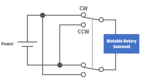
The bi-rotary solenoid is driven by applying voltage to two wires. Depending on the desired rotation direction (CW rotation and CCW rotation), it is necessary to reverse the direction of the current. Please note that the bi-rotary solenoid cannot be driven with an ON-OFF current. By using one 2c relays or two 1c relays, the voltage can be reversed, and the solenoid can be driven.
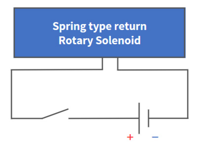
The spring return rotary solenoid operates by turning on the power for the operating side and turning off the power for the return side. However, since there is a polarity for the power supply, please check the external diagram and confirm the color and polarity of the lead wires and the direction of rotation. It can be driven by switching on and off using a relay.
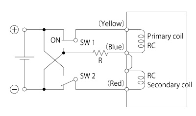
The latching solenoid has three wires. In order to operate stably, it is necessary to connect an external resistor to part R and ground it (to allow the demagnetizing current to flow to release the holding force). There are some solenoids that can operate without an external resistor, but they may not meet the specified suction power.
Please consult us if you cannot install an external resistor.
Durability varies depending on the operating angle and the weight of the load being driven.
Please refer to the general durability conditions and cycles listed below.
[Durability Targets]
Using ball bearings: 30 million cycles
Using oil-impregnated metal: 10 million cycles
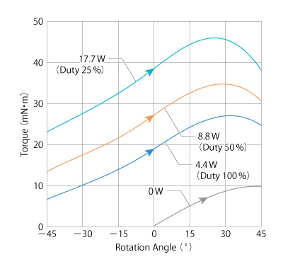
The solid line represents the torque value generated when rotating in the direction from (−φ) to (+φ) during energization (Watt input). When the direction of energization is reversed, it rotates from (+φ) to (−φ) and draws a torque curve that is symmetrical about the rotational angle φ = 0°, as shown by the dotted line. The curve at 0V represents the holding force of the permanent magnet when de-energized. Note that the rotational angle φ = 0° is usually the center of the distribution operation and is the direction indicated by the D-cut of the shaft in the product drawings.
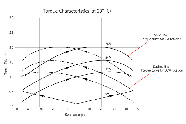
The torque data includes the torque when the rated power (Duty 100%) is applied, and the torque of the maximum power that can be applied during intermittent energization.
For example, when using a rotary solenoid with a rated power (Duty 100%) of 4.4W at intermittent energization Duty 50% (1/2 rated), the maximum power that can be applied is twice as much.
Calculation formula: 4.4W = 8.8W × 50%
Similarly, when using it at Duty 25% (1/4 rated), up to four times the power can be applied.
Calculation formula: 4.4W = 17.6W × 25%
The saturated temperature rise Δθs can be determined with the equation of proportional constant K (°C/W) × continuous power W (watt) × duty cycle (1/f). The proportional constant K (°C/W) of each unit power consumption reaching the saturated temperature rise Δθs is described in the specification tables of each product page.
(Example) In case of RSR20/20-CABO, the proportional constant is approximately K≒7 (°C/W), and the coil saturated temperature rise for continuous power of 10W is Δθs≒7 (°C/W) × 10 (W) = 70 (°C).
Additionally, if the 10W power is driven in intervals of 10ms ON and 10ms OFF, the duty cycle is 1/f = ON time / (ON time + OFF time) = 10 / 10 + 10 = 1/2. Under such intermittent power conditions, the saturated temperature rise is approximately Δθs≒7 (°C/W) × 10(W) × 1/2 = 35 (°C).
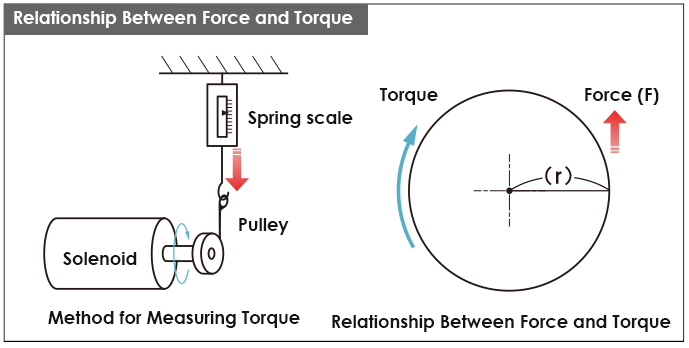
The method for calculating the load torque of the rotating body is as follows.
T = F × r [N·m]
T = Torque [N·m]
F = External force due to the mounting load [N]
r = Radius [m]
Custom designs for shutter shapes, materials, and coating types are available.
Please feel free to contact us.
It is possible. We will confirm the usage conditions and test environment, and provide you with an estimate of the testing costs.
It is possible. We determine the coil resistance value according to your usage conditions, and we accept the production of prototype samples in small quantities.
This is the coil resistance value of the standard product at 20℃.
It can be modified according to the operating voltage, duty cycle, required torque, and other factors.
The magnitude of the counter electromotive force (emf) caused by electromagnetic induction when a change in electric current occurs is a physical quantity. The unit is Henry (H) and it is generated by passive components such as coils. It quantifies the degree of the system's response to changes in electric current and plays an important role in electronic circuits. It is the value at a rotation angle of φ=0°.
The saturation temperature rise of the coil during continuous power application is represented by W (watt). The saturation temperature rise Δθs can be calculated by the proportional constant K (℃/W) multiplied by the power W (watt) during continuous power application and the duty cycle (1/f).
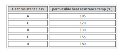
The heat resistance temperature of the solenoid is determined by the permissible heat resistance temperature of the insulation class of the wire used in the coil. Our solenoids are standard in Class E (120°C). We also handle special specifications such as Class H (180°C).
The time from the start of the power input to the end of the operation is represented when the specified angle (°) is operated during the input of voltage.
Please contact our inquiry desk (Contact Us)
