Electromagnetic Actuator Technical Column: From Basics to the Latest Trends Column
How to Install External Stoppers for Bi-Rotary Solenoids and What to Do If It Does Not Operate
Solenoids and actuators are widely used in many aspects of everyday life, such as automatic doors, home appliances, and industrial machinery. They are key components in numerous fields. This column explains how these devices work and in which applications they can be used.
1. Introduction
Customers occasionally inquire about situations where a bi-rotary solenoid “doesn’t move.” This column delves into external stopper installation methods—one potential cause of such malfunctions—and offers support tips to help your solenoid operate smoothly. We hope this information will be helpful.
2. How to Install External Stoppers
1) Condition Upon Opening the Package
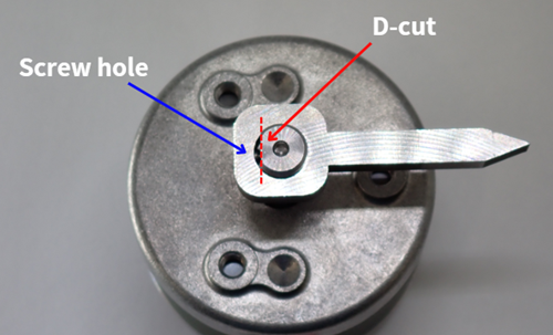
When opened, the permanent magnet and the D-cut on the shaft are positioned in a stable relationship (as shown in Figures F or G below).
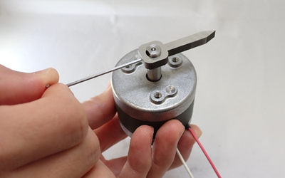
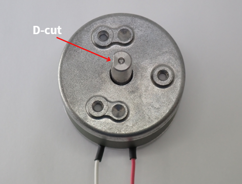 [Appearance of the Solenoid (RSR20/20)]
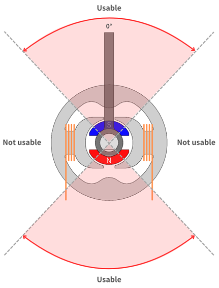
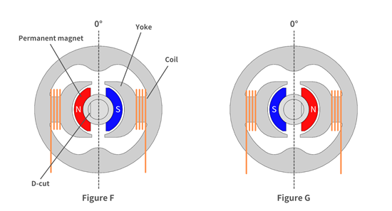 [Cross-sectional View of the Bi-Rotary Solenoid]
2) How to Attach Loads
• Use the D-cut to attach the load (such as a shutter or lever) that will rotate the shaft with a set screw (or by using a “clamp” method). *Choose the appropriate attachment method based on your type of load.
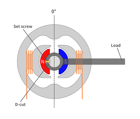 [Cross-sectional illustration]
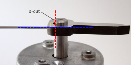
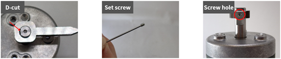 [Key points for installation]
 2. Insert the set screw so that it is perpendicular to the D-cut surface, and tighten it securely.
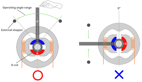
3) How to Install External Stoppers
- Move the load to around the 0° central dividing position, then attach the external stoppers at your required angles.
- The 0° position varies depending on the model, so please refer to the external view in the catalog.
- Once the external stoppers are mounted, letting go of the load will cause it to rotate due to magnetism toward one of the external stoppers.
- The usable rotation angle differs among solenoid models. If you have any issues, please contact us.
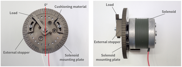 [Appearance upon completing the external stopper installation]
3. Operation Check and Troubleshooting
Should the solenoid fail to operate after completing the above installation, consider the following possibilities:
• Incorrect Energizing DirectionCountermeasure: Consider the following three solutions: 1) Reduce the load. 2) Increase the applied voltage.
[Caution] Increasing the applied voltage also increases coil heat generation. Make sure you do not exceed the rated operating temperature and duty cycle. If you approach these limits, you must either reduce the duty cycle or improve heat dissipation.
3) Narrow the operating angle relative to the 0° central dividing point. A narrower operating angle increases the torque of the rotary solenoid. Adjusting the operating angle as needed can help compensate for insufficient torque.
Countermeasure: Verify that you have correctly installed the external stoppers around the 0° central dividing point for that specific model. You can confirm the 0° position by checking the relationship between the lead wires and the 0° dividing reference shown in the catalog. If your target angles exceed this guideline, try narrowing the angle to see if it will operate as needed.
4. Conclusion
In this column, we presented some best practices for installing external stoppers on a bi-rotary solenoid. We also covered how to check for proper operation after installation and discussed possible troubleshooting methods. By following these recommendations, we hope you can resolve any difficulties in “figuring out how to make the solenoid move” and operate your solenoid smoothly. We hope you find these tips useful.
