What Is a Bi-Stable Rotary Solenoid? Bi-Stable Rotary Solenoid
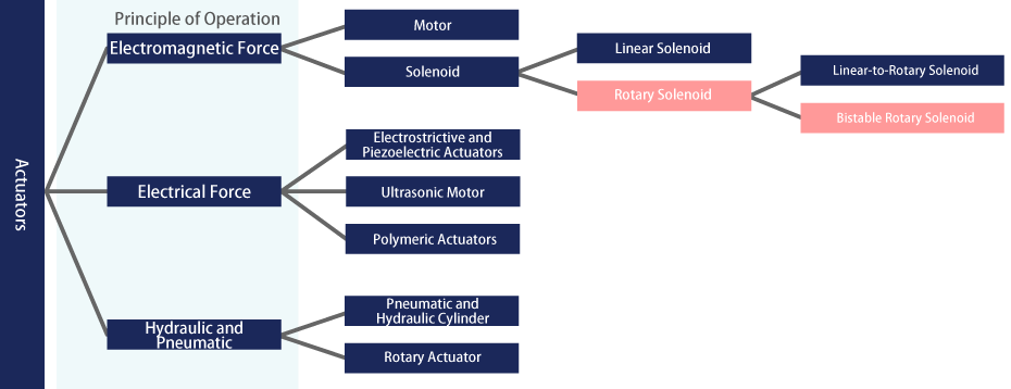
A bi-stable rotary solenoid is an actuator that uses electromagnetic force to perform oscillatory rotation (swing motion), often referred to simply as a rotary solenoid. Unlike motors, which utilize electromagnetic force for continuous rotation, bi-stable rotary solenoids operate within a limited angle range.
Rotary solenoids excel at oscillating between two points. Because they offer high speed and high torque, they are commonly used as a power source for mechanisms such as sorting devices, shutters, or angle-switching drives.
Structure & Features of TAKANO's Bi-Stable Rotary Solenoids
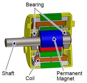
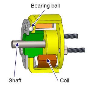
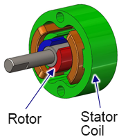
There are two main types of rotary solenoids: one that converts linear motion to rotational motion internally (often referred to as a “linear-to-rotary” solenoid), and another in which the rotor itself rotates directly (the bi-stable rotary solenoid). TAKANO’s solenoids use the latter design, featuring a construction similar to motors.
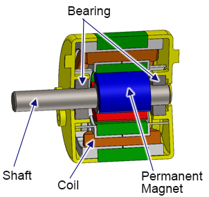
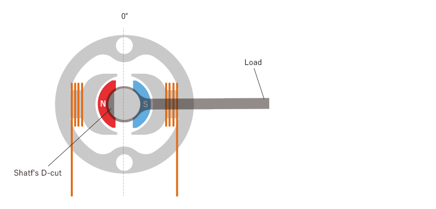
The rotor consists of a permanent magnet and a shaft, with the shaft supported by bearings (ball bearings, etc.) for rotation. The stator contains the coil. By reversing the current to the coil, you can switch the direction of rotation, causing the solenoid to oscillate back and forth.
Feature 1: Non-energized Self-Holding Torque
When the solenoid oscillates between two angles, it can self-hold each position without power. This reduces both power consumption and heat generation.
Feature 2: No Specialized Circuit Required, Easy Control
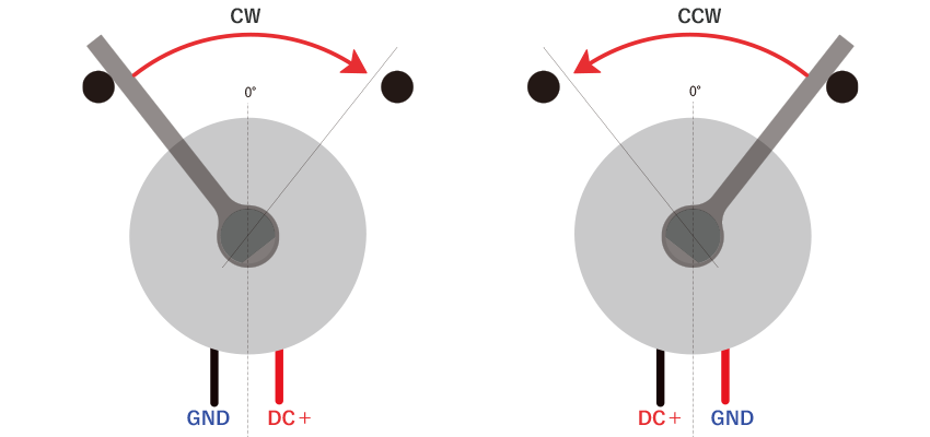
It only requires two wires. Simply switch the polarity of the DC power supply to reverse direction.
Feature 3: Long Service Life
Unlike a brushed motor, there are no brushes, and there is no thrust motion along the shaft. Since there is no contact other than at the bearing, the solenoid’s lifespan depends mainly on the bearing. Using ball bearings ensures a long service life.
Feature 4: Ultra-High Speed Operation
Because rotation is driven by the instantaneous attraction and repulsion of magnetic force, it can operate in under 10 ms response time.
The basic construction differs significantly, and their characteristics also vary. Each type has advantages and disadvantages, so please choose according to your application needs.
Typical Linear-to-Rotary Solenoid
Bi-Stable Rotary Solenoid
Drive Principle
Based on a linear solenoid. The pulling force on the movable part (by coil energization) is converted to rotation via bearing balls and specially shaped ball grooves.
Similar to a motor; the permanent magnet rotor rotates as it is attracted or repelled by the coil’s N/S poles when energized.
Structure
Holding Power (Position Control)
Requires continuous energization for holding, resulting in higher power consumption and heat generation
Self-holds both angles via permanent magnetic attraction, saving energy and reducing heat
*Single-side holding spring-return types are also available
Return Method
Weight (self-weight) of the attached load
Spring-return
Magnetic return (the internal permanent magnet returns it)
Energized return
Spring-return
Energized Torque *Comparison under same size, power, & angle
Strong
Slightly weaker
Shaft Thrust Movement
Moves 1–3 mm in thrust direction, so care must be taken not to restrict axial motion
No thrust movement
Usable Angle Range
0–95°
5–90°
Response Time *Comparison under same size, power, & angle
Slower
Faster
(Especially with dual-direction energization; speed is high in both directions with minimal variance in response time)
TAKANO’s rotary solenoids have a rotor and stator similar to a motor, but the overall structure is simpler.
The rotor is composed of a two-pole permanent magnet, while the stator contains only two-phase coils. This design does not allow full rotation; instead, it provides high-speed oscillation within a limited angle range and offers non-energized self-holding torque.
Example Motor Structures
Bi-Stable Rotary Solenoid
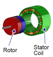
Stepper Motor
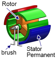
Brushed DC Motor
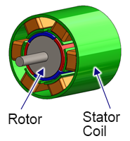
Brushless DC Motor
Representative Structure
Rotor
Permanent Magnet
Permanent Magnet
Coil
Permanent Magnet
Key Features
・Dedicated to oscillatory motion of up to 90°
・Fastest for back-and-forth rotation
・Simple drive circuit possible
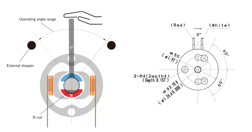
・Requires external stoppers to define rotation angles
・Rotation angle corresponds to the number of input pulses
・Position control is possible with open-loop pulses
・Excels at low-speed rotation
・Requires a dedicated driver and risk of “lost steps” (stall) at high speeds
・Speed and output roughly proportional to input voltage
・Requires closed-loop control with a sensor for positioning
・Low cost
・Brushes wear out, limiting lifespan and requiring maintenance
・No brushes, so longer life and quieter than brushed DC motors
・Requires closed-loop control with a sensor for positioning
・Needs a dedicated driver
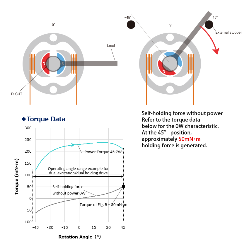
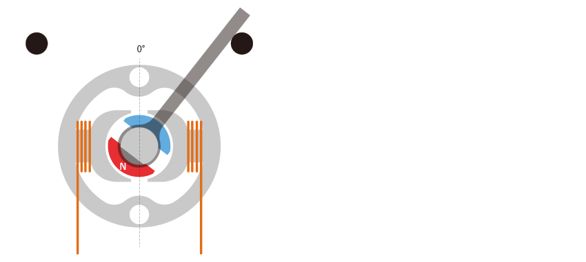
When no current is applied, the permanent magnet rotor naturally settles at the position shown in Figure A, where forces are balanced. If an external stopper is placed as shown in Figure B, the rotor tends to return to the position in Figure A, generating the self-holding torque indicated by the red arrow. The same self-holding torque is produced on the opposite stopper. The amount of holding torque depends on the stopper angle. Refer to each product’s torque characteristic graph for details.
Examples of Non-Energized Self-Holding (Magnetic Return Type)
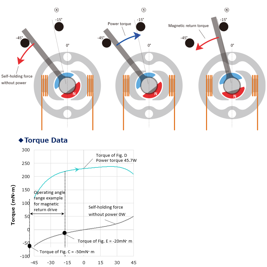
You can also use the permanent magnet's holding force to return the rotor magnetically. This approach limits the usable angle further, but it lets you drive with even lower power consumption by eliminating the need for energizing in the return motion.
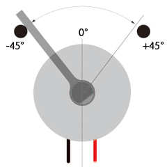
As shown in Figure C, you can place the stopper at -45° and -15° when you want the rotor to pivot 70°, with -45° as one end and -15° as the other. At -45°, a -50 N·m holding torque acts in the CCW direction. When you energize in the CW direction (blue line in Figure D), the rotor rotates until it stops at -15° (Figure E). Once you cut power, the torque at 0 W is -20 N·m, so it returns CCW magnetically.
This design is suitable for fail-safe operation. It also eliminates return springs, offering higher durability without the complexity of spring design and assembly.
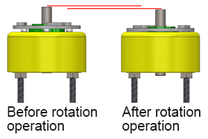
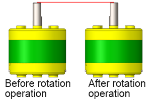
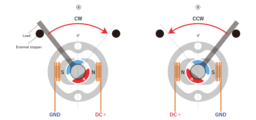
When current is applied, the two-phase coils of the stator become magnetized as N and S poles. The permanent magnet in the rotor experiences attraction and repulsion in that magnetic field, causing it to rotate. Reversing the current flow reverses the rotation direction.
Unless overloaded, the rotor will not stop mid-rotation. Energized torque varies depending on the external stopper angle and the applied voltage. Refer to each product’s torque characteristic graphs for more information.
Bi-stable rotary solenoids offer outstanding performance for limited-angle oscillation or positioning. The following comparison table provides a quick overview.
Bi-Stable Rotary Solenoid
Stepper Motor
Brushed DC Motor
Drive Circuit
○ No dedicated driver required
× Dedicated driver required
○ No dedicated driver required
Rotation Range
× Limited to within 90°
○ 360° unrestricted
○ 360° unrestricted
Position Control
△ Determined by external stoppers
○ Positioning possible anywhere within 360° by input pulse count
△ Positioning requires a feedback sensor (closed-loop)
Positioning Accuracy
△ Depends on the assembly accuracy of the external stopper
○ Very high
× Low
Holding Power for Positioning
○ Holds without power (energy-saving, low heat)
× Requires energization to hold (more power, more heat)
× Requires energization to hold (more power, more heat)
To drive a rotary solenoid, you need three separate elements: a DC power supply, an electrical drive circuit, and external stoppers.
Drive Circuit
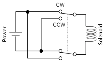
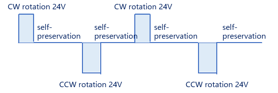
By switching the polarity of the supply voltage using a switch, the solenoid can oscillate back and forth. After movement is complete, you can turn off the power to leverage the solenoid’s self-holding capability, reducing both power consumption and heat generation.
Example of Solenoid Drive Timing
Figure 2 shows a typical drive circuit diagram. We also offer dedicated drive circuit boards for our solenoids.
Installing External Stoppers
Most rotary solenoid models (except for a few) do not include an internal stopper. Please install a stopper to mechanically define the rotation angle.
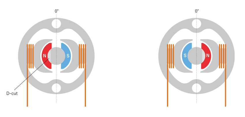
Upon opening the package (with no stopper installed), the permanent magnet and the D-cut shaft will be in a stable position (either Figure F or Figure G), where magnetic forces are balanced.
Attach the load you want to rotate, using the D-cut on the shaft.
Move the load near the 0° position, then install the external stoppers at your desired oscillation angles.
The 0° position varies by model. Please refer to the catalog’s dimensional drawing for the 0° reference. Once the stopper is in place and you release the shaft, the rotor will snap to one of the stopper positions due to magnetic force. Note: Use cushioning (e.g., rubber) for the stopper. Metal-to-metal contact can cause strong impacts and lead to damage.
Installation is complete. If the solenoid does not move when energized, possible causes include:
① The polarity of the power supply is reversed.
→ Solution: Reverse the polarity and check operation.
② The load is too large.
→ Solution: Reduce load, increase supply voltage, or reduce the rotation angle.
③ The stopper positions are incorrect.
→ Solution: Confirm that the external stoppers align with the 0° reference for your model.
④ The D-cut orientation does not match the 0° position.
→ Solution: Verify that the D-cut orientation aligns with the 0° position.
Step 1: Decide Your Stopper Method & Rotation Angle
Choose the rotation angle based on your application needs.
In addition to the standard dual-self-holding configuration, you can select a more limited angle setup to reduce power consumption by using magnetic or spring return. This allows you to reduce or eliminate energization during return motion.
Dual Self-Holding
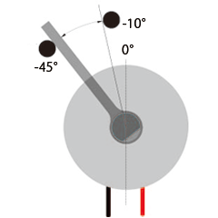
Magnetic Return
Spring Return
CCW Magnetic Return
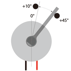
CW Magnetic Return
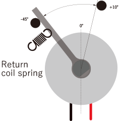
CCW Spring Return
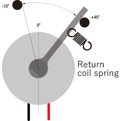
CW Spring Return
Features
・Most common drive method
・Allows largest usable angle
・Self-holds at both angles
・Reduces power consumption by relying on the permanent magnet for return movement
・No need for springs or other mechanical return methods, improving durability
・Enables fail-safe design if power is lost
・Uses a spring for return, reducing power consumption vs. dual-self-holding
・Less reliable than magnetic return but supports a wider angle
・Enables fail-safe design if power is lost
Non-Energized Self-Holding
Left stopper: Self-holding
Right stopper: Self-holding
Left stopper: Self-holding
Right stopper: No holding
Left stopper: No holding
Right stopper: Self-holding
Left stopper: Spring force
Right stopper: No holding
Left stopper: No holding
Right stopper: Spring force
Approx. External Stopper Angles
Up to 90°
Left stopper: -45° or above
Right stopper: +45° or below
Up to ~35°
Left stopper: -45°
Right stopper: -10°
Up to ~35°
Left stopper: +10°
Right stopper: +45°
Up to 55°
Left stopper: -45°
Right stopper: +10°
Up to 55°
Left stopper: -10°
Right stopper: +45°
CW Rotation (Right Rotation)
Energized
Energized
Magnetic Return (No power)
Energized
Spring Return (No power)
CCW Rotation (Left Rotation)
Energized
Magnetic Return (No power)
Energized
Spring Return (No power)
Non-energized Spring Return
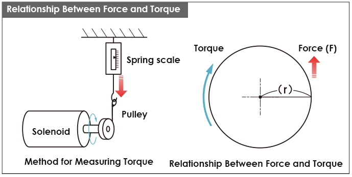
Step 2: Calculate the Required Torque
Calculating load torque:
T = F × r [N·m]
T = torque [N·m]
F = external force from attached load [N]
r = radius [m]
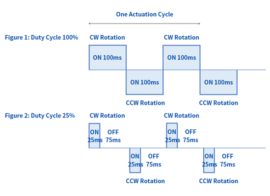
Step 3: Calculate the Duty Cycle
Because bi-stable rotary solenoids can maintain position via permanent magnets, you can keep them unpowered when not moving.
The duty cycle refers to the percentage of energization within one operation cycle. It is calculated as follows:
ON time = time the solenoid is powered
OFF time = self-holding time
Duty Cycle (%) = ( ON time / (ON time + OFF time) ) × 100 (%)
In Figure 1, the solenoid is energized continuously, so the duty cycle is 100%.
In Figure 2, the duty cycle is 25%.
Step 4: Select the Model from the Torque Characteristics Based on Steps 1, 2, & 3